Sunday, 19 January 2014

Updates to the Drawing Module

I'd promise to get some wrote by the end of the week, so here's my attempt on covering updates I have made to the Drawing Module over pretty much the last half of the year.

In general there's been a lot of incremental small fixes that have accumulated over such a long time, which is a stark contrast when I look at the last blog post on this and might seem significant.

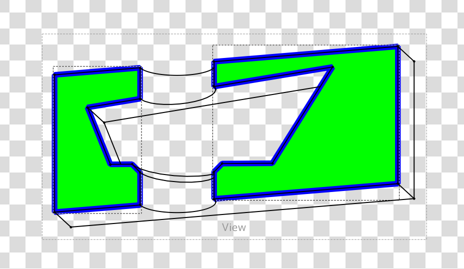
One of the big changes was adding initial support for drawing the page background given the width and height and recently spending time switching the origin of the coordinate system to the bottom left with the y-axis pointing upwards - see this post. QGraphicsView orients with the y-axis pointing downwards which is also used in SVG. It's a trivial fix, where the y coordinate is inverted for the position of every Drawing Views. This is needed to ensure consistency with CAD packages and other formats.

The next step for improving the functionality is adding support for templates and displaying this on the background.


These leads onto talking about further work on improving the dimensions. The most obvious detail is the improved presentation of dimensions. There are now arrow heads, which later will be allowed to be changed to a few standard ISO options and the use of a font called osifont, which I was recommended for a starting point for datum labels. The license needs checking as it appears to be GPL 3 - I'm not entirely sure if this is compatible for distribution directly with the FreeCAD release but in the worst case an be installed separately by the user or made a dependency on the packaging front and be used if available by default.


The datum values can be used calculated as project or as true values - if an orthographic projection is used then projected values are used by default. The leader lines are also calculated to the end points of the lines avoiding any overlapping. The dimensions also use caching and now don't need to recalculate when these are moved on the canvas by the user. 


There is now an orthographic container, which contains ortho-views -orthographic projections such as front, left, top etc. These benefit of having a container is that the child orthoviews are much smarter and allow various properties such as scale or the type of projection (first or third angle) to be set from the container which are then cascaded down to the child views. 

QGraphicsView is quite flexible and allows some nice interactivity too. A little feature I implemented was having alignment between views: and can be interactively moved along one axis. You can seen in the screenshot from above the are all aligned correctly. This originally took a while to figure out because the projection used in the current release of FreeCAD is not consistent - the simple trick was ensuring that the centroid of the part is used as the origin of the projection plane. 


Another little feature I added was support for angles - although there are a few cases where an exception is thrown. The final thing I currently can think of working on is improving the print support which is slowly getting there:


Anyway that's an overview and hopefully give some incentive to give the drawing branch another try!


Monday, 13 January 2014

I'm back!

I took some time of for the later part of 2013 for an adventure that in the end didn't work out. Boo hoo!

Now I'm returning back again for 2014 for the foreseeable future! I'm pleasantly surprised to see that people are still actively looking at the pages - despite the inactivity since May and it's remarkable how time has flown. Anyway, let me introduce the new year with some good news.

From last December, I am now a Postgraduate Research student at the EPSRC for Innovation in Additive Manufacturing at the University of Nottingham. (This means I'll be working for a PhD over the next three years). It is a great opportunity to be doing particularly ground breaking research here on various areas concerned essentially with commercial 3D printing and eventually become an expert in this revolutionary field. 

As with all academic research this is non-proprietary, so in theory the modelling techniques that we are aiming to develop may reach into programs such as FreeCAD. I'll later give a brief overview of what we do here now I'm familiar with what projects have been taking place.

I'll later incorporate other posts into this blog related to my research but not exclusive to FreeCAD that might be of interest to some readers. Later on I hope to apply some experiments too. 

So where do I position my self now with FreeCAD? Admittedly these days, I don't have as much time as an undergraduate during the day, but I now have blocks in the evening where I can sufficiently give time to work on it as I choose. 

Drawing Module:

My focus is to tidy up the work that I've done over the past year on the new Drawing Module and get it into a 'playground' state where interested users can test and use it with the strings attached that non-critical bugs exist.

Later on in the week I'll try and write up an update of where I currently am with the Drawing Module - obviously with pictures!

The current big show stoppers in terms of stability and usability are the following:
  • Random Draw Crashes (rare)
  • Random segfaults (rare)
  • Some projections are missing (tangent curves in particular)
  • Dimension of edges lose their position randomly (Bug with OpenCascade)
  • Background template layer non-existant
Note to people: There has been many substantial changes since May. Feel free to check out the git repo - Drawing branch and try it out! 

If you can find some solid test cases for the above in particular that would be very helpful :) 


Friday, 31 May 2013

Exams are finished

Yesterday was a momentous occasion. Completing my last exam, I have now finally completed the four years of my degree studying Mechanical Engineering. I guess that's party time for me!

With the unpredictable and quite volatile nature of British weather, there are bound to be a few days that will be pouring with rain, hence an opportunity for further work on getting this drawing module completed.

Over the past week, I have been making a few small refinements, consisting of fixes:

* Preventing a segfault when creating a dimension
* Fix for incorrectly placed dimension - was difficult to locate the bug
* Fixed a rounding error which meant decimals were not being displayed

Dimensions Arrows:

I have also added a support class for displaying dimension arrows, although these are just diagonals at the minute.

'

Having a separate QGraphicsItem class is more useful as it keeps the source code tidy by having the drawing code separate. Also it gives flexibility to manipulate the arrows, such as scaling, flipping etc more universally.

It would also be nice to get the page template working again, but waiting on some work to be ready!

Projected Dimensions:

I spent of time to work on this. Originally I thought this was going to be a difficult task. I thought that to get projected dimensions, I would have to make measurements of projected geometry, which would have been laborious to do. Instead, a quite simple solution is to use the same measurement code for true lengths, but project the measurement vector (direction and length) onto the view plane. Taking our complex case below, there will be a difference between true and projected dimensions.


Taking the top projection of this object and taking dimensions for the corner of each pad the result is below.


The dimension on the far left is the true length, and the right is the projected length. I have attempted to make all dimensions which reference orthographic views to use projected type. 

The next step is to work on getting edge to edge dimensions and angles working. The angles bit is more complicated because the angle value measured is based on the quadrant chosen. 

Wednesday, 22 May 2013

Quick experiment again with Sectional Views & General Updates

I am midway during exam season (two weeks) long and things seems to be going swimmingly which I'm happy to report.

Over the past two weeks I've just spent some time tidying up the code and trying to fix a pretty nasty crash in QGraphicsview, anytime you updated the view. I really hope this has gone, but if during testing you suddenly experience a crash when the view updates, please inform me. It seems to have disappeared but esentially was a problem with incorrect bounding boxes as the usual case is. Additionally I've just tidyied up the code and improved the performance by having QGraphicsView using a backend cache, so it doesn't have to constantly redraw features when it is unecessary.

Today, I decided to have a day off revision, as to be honest I am fed up with the mundane repetitiveness. Apart from what I mentioned earlier I wanted to take a quick diversion from the orthographic project stuff I've recently been looking at which I've also made a few improvements on.

I wanted to take a look back at sectional views which I had to give up on because I couldn't correctly produce faces by processing each edges in the correct order. I mentioned this in a previous blog entry some time ago.

Eventually I managed to find the problem and unexpectedly half of the result was from the drawing code itself, where although the edges were in the correct order there was a chance these could be reversed.  Eventually I got something working on most faces.

I then updated the work on the sectional view and behold...


This was taken from a simple planar cut through straight through the centre:


To be honest it's only a proof of concept that i've created over the past few hours. I have identified that some changes are needed to improve the structure to something less 'hacky'. The other limitation is there won't be use of 'true' dimensions because references are lost when the boolean cut is applied.

----------- UPDATE ---------

We all like updates. Spent this evening on it again, rather naughtily and tidied up the areas that I weren't happy with. The section plane is now it's own object in the drawing view, so I had to build up some infrastructure around there which I am more happy with. Now we can finally get some sectioning goodness!


I need to fix a bug that's causing a segfault, so hopefully soon I can push this for people to try and experiment with probably more complicated shapes. 

Friday, 10 May 2013

First work on Orthographic Projections

Having had a bit of a day off, I spent some time working on Orthographic projections with the Drawing Module. One of the problems with the older implementation was that only a projection direction was provided. This meant that the GUI / SVG had to deal with applying transformations to obtain the correct projection which isn't really ideal. All this took a while to realise, however, both the projection direction and its orientation (X-Axis) can be set during the Open Cascade Projection Algorithm.


The result is above and it later will allow more convenient production of orthographic projections, by setting the view type below.


The next step is to collect these orthographic projections together and allowing having these align to each other. 

Friday, 26 April 2013

Drawing Updates & Bloodhound SSC


Pardon me for starting the post off-topic, but last night I went to a talk given by Richard Noble the director of Bloodhound SSC (below), aiming to achieve Mach 1.4 or 1000 mph (~1600km/h ). I freely admit it was an inspiring talk and especially given how little I knew from the small excerpts produced by IMechE - UK's institute for Mechanical Engineering, it provided to be very informative.
Bloodhound SSC
Why I raise this, is that one of the key emphases on the talk is about inspiring the next generation of Engineers not just in the UK but all over the world - akin to Nasa's Moon Landing Programme in the 60's. We share a responsibility as engineers to foster the development of the youth. Many open design such Raspberry Pi and Adruino  are sharing such successes involving children and young adults alike.

Without becoming too philosophical, FreeCAD would be part of this idealistic goal. Being able to provide free but importantly open tools that I never had when I was at school would bring opportunities I wouldn't have dreamt off - I was the one of the last generation at our school to produce hand-drawn drawings, which shockingly was only six years ago.

Ultimately if you cannot contribute to FreeCAD as a programmer, there are endless ways you could help and I wish to thank the members of our community for doing so without initiative!

Back on topic: Drawing Tweaks and Updates

Probably the biggest changes came last night and was most surprisingly because of the fact how tired I was. The Drawing View (QGraphicsView) updates itself when you change it's property, this includes dimensions too and surprisingly works very well. Additionally the drawings are correctly created when you restore a document. 

Hopefully I'll publish a video to better demonstrate this, because  find it a satisfying result.

The other changes is scale independent rendering, edges retain the same stroke width regardless of the document zoom.All this we get for (nearly) free in QGraphicsView! There's a problem with selection at the minute, but hopefully will be sorted out soon (Fixed). I don't believe this is easily done using SVG because transformations are applied at object level. 


The example of above scales as you would expect, which was scaled really small on my screen but is not desirable in CAD drawings. You don't want lines to obscure each other when you zoom in, especially on an extremely complicated part with greater detail such as below.


I've also added a scale option. This currently transforms the original FreeCAD Part, however, I am still unsure is the best approach in terms of performance which could be natively applied in the projection algorithm. However, now it appears to work correctly.


In the previous drawing module the scale was applied at the presentation layer in SVG and wasn't really the best solution although it worked.

I wanted to put a picture up but I am currently upgrading Kubuntu. It will most likely not go smoothly, but atleast I'll be ready to report any problems compiling with FreeCAD.

Taken a short screen cast to show off the Drawing Module in it's current state. Only had 15 minutes to make it this morning, so sorry for the lack of quality!


Note: The drawing artefacts appear when recording the video for some reason but otherwise are not there normally.


Saturday, 20 April 2013

Finally we have arcs that work!

For over a month this has been a problem where on 3D projections, arcs are turned into partial ellipses but were being incorrectly drawn. Attempts to diagnose the problem were unproductive - see the forum topic

There a sudden moments that make you realise that perhaps there is an easier way, just like last night. I though of mimicking the previous code that generates SVG directly. Instead of creating an actual ellipse arc, an cubic arc is produced instead - see the Mozilla Docs.For Qt to render SVG it must process this, so that there must be a method for drawing these somewhere. After some searching I found a function available in qsvg/qsvghandler.cpp. This had what I desperately needed and thanks to Opensource is possible.

Literally copy and pasting the relevant code - later will be re factored to be simplified if possible, this morning I got it working and produced the results I was craving!

This accomplishment crowns the ending of my Easter Vacation. I return to University tomorrow.

The couple of bigs tasks remaining are growing smaller. Ideally, I need the drawing to update automatically by itself, but changes don't propagate into non-3d views. Also we need working templates - looked at by Joshua.

The other is re-doing the export code - we get .svg and .pdf free with QGraphicsView, but .dxf.One thing I am going to enquire is an export to librecad. dxf sounds like the devil, so I think promoting an open format would go well.

The remainder should be smaller jobs that other people could get involved with. By then I hope I could get this be ready for testing by mid-summer. 

Thursday, 18 April 2013

Little updates

Spent the past few days tidying up the Drawing Module as a needed break from revision.


It is starting to come together:

  • Added support for radius dimensions on arcs.
  • Added support for point to point dimension
  • Improved selection of edges and vertexes
  • Antialiased Edges
For an hour I spent adding a nicer selection box for moving a views around which definitely helps prevent annoying selection of the view. 


Dimensions are coming together too quite nicely, although the radius dimensions don't work yet in 3D view. I probably add some arrows, but these are not high priority. 


I've started the work on correctly showing hidden lines. I am pretty pleased with the result. I have opted for selecting the whole edge (visible and hidden), hopefully that seems reasonable.


I was slightly disappointed to find that references for some edges cannot be find in 3D views, however is a limitation imposed by Open Cascade. If a reference cannot be found, these edges are not selectable, since they cannot be used for any measurements. One possible idea to circumvent this problem is to compare the projected edges with references to edges on the original geometry that weren't found. This isn't really ideal, but would be a temporary solution.

One of the other problems is ellipse arcs which still I cannot figure out.

Friday, 12 April 2013

Parametric dimensions in the Drawing Module


After about three weeks, of having to work on various assignments (nearing completion) and revision, I finally had a day off to work on dimension support in the Drawing Module (see above and compare to previous post).

Obviously the dimensions look much better and are correctly positioned and it also shares similar behaviour to sketcher where if the datum label lies outside the arrow lines change position accordingly.

Additionally the dimension can be set to the edge length in X or Y direction now quite easily by changing the dimension mode. Currently the dimensions only work for Straight Line edges, but I plan to address some support for vertexes and obviously circular arcs.

One of the interesting things that had to be thought was how to reference edges that are broken up into smaller segments by any geometry in front.


My first attempt at this failed miserably, where I thought I would reference each segment of the edge and find the ends from there but clearly it wouldn't work. After scratching my head, I thought the best way to go was getting the reference to the original geometry and projecting the whole edge and using this instead for dimensions.

The limitation with this strategy is that if the original reference isn't available you won't be able to get true parametric dimensions. Generally this isn't a problem - nearly all the time I have found references are available and if they aren't usually it is for curves projected onto a 3D view.

It was a bit of work to get to work, because I was using HLRBrep_Curve and that require figuring out what type of curve was produced when finished. I kept to this OpenCascade Algorithm to allow perspective projections if they were ever needed. Luckily it worked!

Behold Parametric Dimensions!

The big test really was to change the projection direction and see what happens...


And yes it worked - although the datum label positions need correcting, nothing else had to be changed. Now changing the geometry (nothing too drastic)...


It's a pleasing result because it's been several months in the works to get this working, not knowing if this would be even possible. Obviously there's a lot left to do.One of my biggest problems at the minute is that if there are changes in the Document Structure, the drawing view must be closed and re-opened

The next priority is to tidy the module up more as it's still feels experimental.


Sunday, 17 March 2013

First step of having DImensions in Drawing Module


Spent today working on adding dimension support. The first results are in and are quite pleasing. The dimension lines aren't correct but do indeed move interactively and the values for the dimensions update with changes basic changes in geometry. Obviously this is no where near being done, but is a step in the right direction once again.

-----
One area that does become problematic is making large changes in the geometry, and will be quite troublesome to deal with, even with robust naming. This should be a problem with vertices. because they cannot be decomposed further. 

Currently dimensions refer to the individual projected edge, or vertex because in theory multiple projected curves could exist. This needs further thought, but perhaps the best solution is consider merging projected edges together which share the original reference to the object and then having dimensions refer to these instead. Any ideas?