Showing posts with label Orthographic Projections. Show all posts

Monday, 12 May 2014

Drawing Updates

I've returned from an interesting cycling vacation in Europe and if I can call myself rested, it helped provide me with a bit more energy to gear me towards getting the Drawing Module finished.


With a steady stream of testing, I have been ironing out some long standing issues, some hidden bugs and adding a bit more functionality. Fuelled by beer and eagerness to get this module complete, there's been some steady progress over the last week - or if deemed worthy a coding 'sprint'.

There have been a substantial number of changes since last time, both visible and under the hood. I'll try my best to highlight the most important changes:

With anything this creates new bugs and also helps discover ones hidden away. I think the philosophy is starting to come true: you complete 90% of your project in 10% of the time and the remaining 90 % of time is spent debugging the remaining 10% .

New Features:

Drawing Icons

Drawing Icons are now used to represent objects in the drawing. Courtesy of Jim!


Dimensioning tool bar

You may now select specific dimensions for your drawing

Diameter constraints

I recently added a diameter constraint which has various positional arrangements depending where you position the dimension label. 

Centre mark option available for diameter and radius dimension


Drawing is updated dynamically when changing properties using property editor


Orthographic Task View Dialog:

Due to architectural changes,l the previous task dialog coded by Joe was difficult to incorporate with what I had done.  The difference now is the way views are now handled positioning and views are managed with a container object (Orthographic projections) - this allows you to set the scale for each individual view and eventually the projection type. 

These are automatically updated in real time. Along with this there are now three different scale types: 'Document' uses the page scale, 'Automatic' will attempt to calculate this automatically and also custom option. The latter two are available for all views.


Undo & Redo now possible

Before this was a notable problem where it was never guaranteed that you could undo and redo correctly. It appears to work very well under most situations - even deleting items. The only issue I have seen so far is when deleting a dimension this isn't correctly positioned when you try to redo operation. 

Improvements

  • Select 'anchor' view and now correctly drags the group
  • Drawing dimensions don't recalculate every time they are moved.
  • Dimensions correctly positioned when you save and restore the document. 
  • Reduction in number of document.recomputes - updates are automatically made. 
  • Vertical and horizontal dimension is checks edges are not zero
  • When you  create a page using the tool bar, the template is now loaded for the page (A4/A3) chosen
  • Tangent edges (e.g. cones, fillets) should now appear after disabling a check. Note: there is a limitation that these cannot be dimensioned

Reliability:

These are some recent changes this morning to try and prevent the random crashes/segfaults from occurring. As a result the bounding box also includes dimensions. I'm not sure if this is a good thing but I just need see if we still experience random crashes. This was a notable problem encountered in particular when you dragged a drawing view or more likely deleting a view. If I can get feedback on this over the course of time it'll help diagnose a better solution.

There  are more bugs out there some I'm aware of and some I'm not and to coin a nostalgia phrase we 'gotta catch em all'

Saturday, 15 March 2014

Drawing Updates

I am in the stage of trying to tidy everything up and get this baby into testing for you people to enjoy.

I noticed that the drawing performance in QGraphicsView was becoming very slow especially if you tried to zoom in. It wasn't really obvious why but through investigation I noticed that this was because of a QGraphicsItemRectangle that was being used to render the blank page background. This was even with caching enabled and redrawing seemed to persist which was the cause of the performance penalty observed.

The improvement I made was drawing the background page (a white rectangle) in the QGraphicsView drawBackground method. Instantaneously the performance was improved irrespective of zoom level. Everything comes at a price. The caveat was that we don't have a shadow for the background, but the main issue was very random segfaults. After hours of probing, it the cause was peculiar. An empty QGraphicsItemGroup was not updating its bounding box correctly. In short this got fixed with ample amounts of frustration. What is also nice is that much of the Drawing Canvas is cached so there should be little redraw slowing us down.

As a result the performance is significantly better and the user interaction on my computer is smooth.

I also was investigating the Task View created by Joe to see what can be used to create organised orthographic projections. Much of the functionality is built already in at a lower level except the automatic scaling. It's in all best interests to use code, but I am in the position where it might be easy to start with a simple interface that doesn't have all the logic embedded inside it. I'll post a topic on the forum for people's thoughts.

Through this investigation, now in a collection of Orthographic views it has an anchor view which is used to move the whole group. It already feels quite intuitive to use. This was misleadingly obvious to implement and I started off using Qt's signal and slot mechanism but this was causing a reciprocal effect, whereby movement was  exaggerated. After a few beers, I stumbled upon QGraphicsSceneMouseEvent::ignore() which allows a child items event to bubble through the child-parent hierarchy. To my surprise this work instantly and was also smooth.

Getting bored one evening, I wanted to experiment and see if we could have user-editable text fields for the SVG templates, rather than the cumbersome Property Editor. To my surprise it's quite straight forward using previous code and using the text elements in the SVG document to create QGraphicsTextTtem which can be used very easily.

Time for screenshot!


The picture above is a culmination of what's been done. The text block on the right were edited in the document. All that needs to be figured out is if people are happy with this and a mechanism for storing the data fields more intuitive than an array. 

Friday, 31 May 2013

Exams are finished

Yesterday was a momentous occasion. Completing my last exam, I have now finally completed the four years of my degree studying Mechanical Engineering. I guess that's party time for me!

With the unpredictable and quite volatile nature of British weather, there are bound to be a few days that will be pouring with rain, hence an opportunity for further work on getting this drawing module completed.

Over the past week, I have been making a few small refinements, consisting of fixes:

* Preventing a segfault when creating a dimension
* Fix for incorrectly placed dimension - was difficult to locate the bug
* Fixed a rounding error which meant decimals were not being displayed

Dimensions Arrows:

I have also added a support class for displaying dimension arrows, although these are just diagonals at the minute.

'

Having a separate QGraphicsItem class is more useful as it keeps the source code tidy by having the drawing code separate. Also it gives flexibility to manipulate the arrows, such as scaling, flipping etc more universally.

It would also be nice to get the page template working again, but waiting on some work to be ready!

Projected Dimensions:

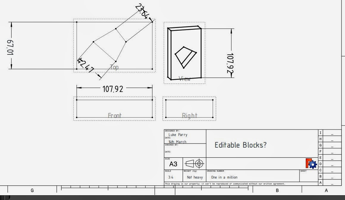
I spent of time to work on this. Originally I thought this was going to be a difficult task. I thought that to get projected dimensions, I would have to make measurements of projected geometry, which would have been laborious to do. Instead, a quite simple solution is to use the same measurement code for true lengths, but project the measurement vector (direction and length) onto the view plane. Taking our complex case below, there will be a difference between true and projected dimensions.


Taking the top projection of this object and taking dimensions for the corner of each pad the result is below.


The dimension on the far left is the true length, and the right is the projected length. I have attempted to make all dimensions which reference orthographic views to use projected type. 

The next step is to work on getting edge to edge dimensions and angles working. The angles bit is more complicated because the angle value measured is based on the quadrant chosen. 

Friday, 10 May 2013

First work on Orthographic Projections

Having had a bit of a day off, I spent some time working on Orthographic projections with the Drawing Module. One of the problems with the older implementation was that only a projection direction was provided. This meant that the GUI / SVG had to deal with applying transformations to obtain the correct projection which isn't really ideal. All this took a while to realise, however, both the projection direction and its orientation (X-Axis) can be set during the Open Cascade Projection Algorithm.


The result is above and it later will allow more convenient production of orthographic projections, by setting the view type below.


The next step is to collect these orthographic projections together and allowing having these align to each other.