Showing posts with label QGraphicsView. Show all posts

Saturday, 15 March 2014

Drawing Updates

I am in the stage of trying to tidy everything up and get this baby into testing for you people to enjoy.

I noticed that the drawing performance in QGraphicsView was becoming very slow especially if you tried to zoom in. It wasn't really obvious why but through investigation I noticed that this was because of a QGraphicsItemRectangle that was being used to render the blank page background. This was even with caching enabled and redrawing seemed to persist which was the cause of the performance penalty observed.

The improvement I made was drawing the background page (a white rectangle) in the QGraphicsView drawBackground method. Instantaneously the performance was improved irrespective of zoom level. Everything comes at a price. The caveat was that we don't have a shadow for the background, but the main issue was very random segfaults. After hours of probing, it the cause was peculiar. An empty QGraphicsItemGroup was not updating its bounding box correctly. In short this got fixed with ample amounts of frustration. What is also nice is that much of the Drawing Canvas is cached so there should be little redraw slowing us down.

As a result the performance is significantly better and the user interaction on my computer is smooth.

I also was investigating the Task View created by Joe to see what can be used to create organised orthographic projections. Much of the functionality is built already in at a lower level except the automatic scaling. It's in all best interests to use code, but I am in the position where it might be easy to start with a simple interface that doesn't have all the logic embedded inside it. I'll post a topic on the forum for people's thoughts.

Through this investigation, now in a collection of Orthographic views it has an anchor view which is used to move the whole group. It already feels quite intuitive to use. This was misleadingly obvious to implement and I started off using Qt's signal and slot mechanism but this was causing a reciprocal effect, whereby movement was  exaggerated. After a few beers, I stumbled upon QGraphicsSceneMouseEvent::ignore() which allows a child items event to bubble through the child-parent hierarchy. To my surprise this work instantly and was also smooth.

Getting bored one evening, I wanted to experiment and see if we could have user-editable text fields for the SVG templates, rather than the cumbersome Property Editor. To my surprise it's quite straight forward using previous code and using the text elements in the SVG document to create QGraphicsTextTtem which can be used very easily.

Time for screenshot!
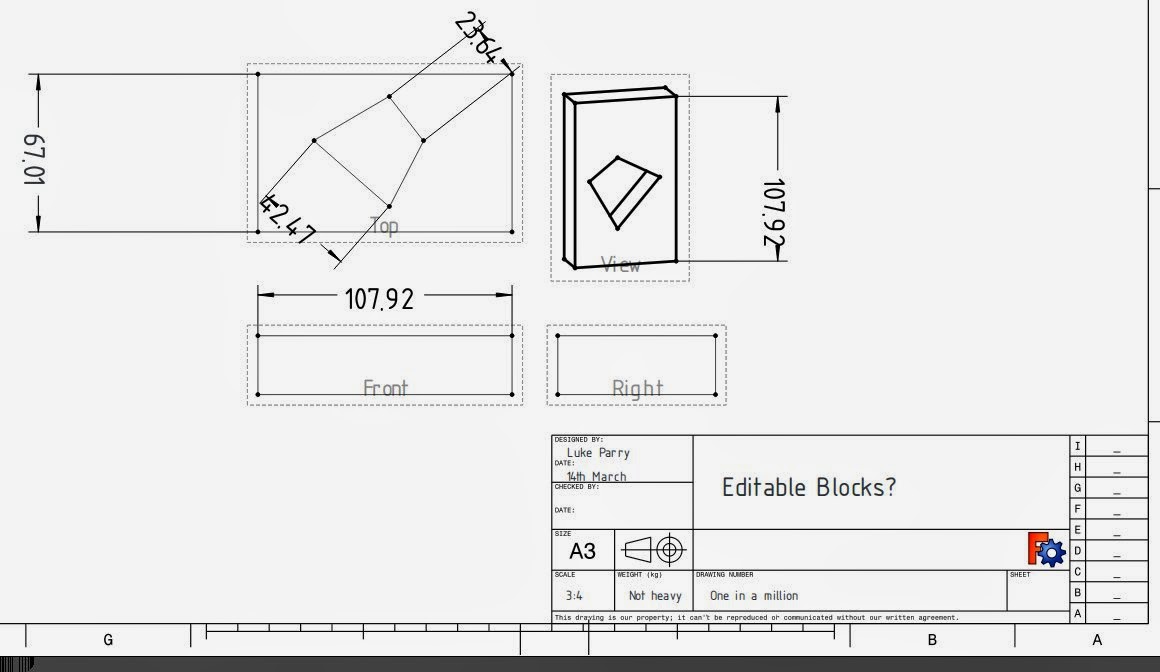

The picture above is a culmination of what's been done. The text block on the right were edited in the document. All that needs to be figured out is if people are happy with this and a mechanism for storing the data fields more intuitive than an array. 

Friday, 7 February 2014

Beginning of parametric (python) templates in the Drawing Module

It's been a passing since the last entry. Unfortunately I've run out of beer and the fridge is empty, so tea again will suffice for a quite casual evening in programming.

After some discussion on the forums, I think I eventually persuaded everyone that SVG templates are simply not right for the job. Admittedly it's a nice standard and is great for customisation and has worked very well in the previous version available in FreeCAD. It also allows easy customisation and post-editing with other graphical editors such as Inkscape.  In fairness, Inkscape was not built for this job, even if there are several attempts at adding CAD functionality into the mix.

The problems using SVG for templates as I see it:

As far as I'm aware it's not adopted by any Mechanical CAD Package. I won't get into the discussion, but the biggest problem with using this template format is that there is no easy way to translate this into other formats such as .dxf, .dwg (Autocad / Teigha) or even our own representation if we ever needed it.

Dealing with XML is not impossible, and can be quite easy to manipulate using DOM (Document Object Model) functionality built into Qt. However, interacting with it through QGraphicsView is not great even if we have QSvg - which is apparently now obsolete. The other original idea was to parse any text fields and turn these into editable text boxes, but this alone creates further impracticalities.

The other big problem that seemed to be happening was the size and variation between templates based primarily on the paper size and the standard used (ANSI, ISO, Arch). There is nothing stopping someone creating these but in the future if these maintained it creates a lot of duplication of work.

I decided that we might as well do it RFT (right first time) rather than wait after the maiden release of the new module, which could be later in the year now.

Parametric driven templates

The combination of having endless combinations of templates was impractical. Some professional Mechanical CAD systems actually have limited number templates available. Instead, there was an attempt to to generate the SVG template using a python script. In the end. the best solution is to use a customisable python script to automatically generate the geometry, text fields and other extras for the template.

This script runs each time page dimensions change and is passed important properties such as page type, width, height, fields required and can create the frame, title blocks and so on, to the user's liking. I'd envisage an interface panel for customising this.

Any template geometry, fields etc. are abstract entities and are stored within the document feature. This can be then easily processed by an export script to be usable in different file formats.

Having abstract types allows isolation of individual elements in a template much easier. Practically this means if a text field is created, a text editing place holder is created and can be more easily manipulated. The same will go for Template annotations which still need work.

The only problem with this method, is we are somewhat restricted to the drawing functions and data types implemented. This might be lines, rectangles, arcs, text. Some CAD programs allow their sketch functionality to be used on top of their drawings. In some cases it can be quite useful, however, considering the maturity of the module, I don't think is appropriate or demanded.

I'll shut up now and show a picture.


This is a square page with a isometric view on it. Those lines across the page were created using

App.ActiveDocument.Template.drawLine(x1,y1,x2,y2);
App.ActiveDocument.Template.touch()

I'm still not sure yet how to organise the script so it knows about Template. However, this is to just show it working. I'm looking for people who can parametrically create a nice python script for generating scripts - don't expect me touching python!

Dimension Placeholders:

Some people will like this. From a solidworks background you can use custom placeholders for dimensions/sketcher datums. It's quite neat and allows some customisation where you may need it. 

For now my implement uses placeholders where there is a content field and the placeholder %value is the datum size.

That's all for  now folks!

Sunday, 19 January 2014

Updates to the Drawing Module

I'd promise to get some wrote by the end of the week, so here's my attempt on covering updates I have made to the Drawing Module over pretty much the last half of the year.

In general there's been a lot of incremental small fixes that have accumulated over such a long time, which is a stark contrast when I look at the last blog post on this and might seem significant.

One of the big changes was adding initial support for drawing the page background given the width and height and recently spending time switching the origin of the coordinate system to the bottom left with the y-axis pointing upwards - see this post. QGraphicsView orients with the y-axis pointing downwards which is also used in SVG. It's a trivial fix, where the y coordinate is inverted for the position of every Drawing Views. This is needed to ensure consistency with CAD packages and other formats.

The next step for improving the functionality is adding support for templates and displaying this on the background.


These leads onto talking about further work on improving the dimensions. The most obvious detail is the improved presentation of dimensions. There are now arrow heads, which later will be allowed to be changed to a few standard ISO options and the use of a font called osifont, which I was recommended for a starting point for datum labels. The license needs checking as it appears to be GPL 3 - I'm not entirely sure if this is compatible for distribution directly with the FreeCAD release but in the worst case an be installed separately by the user or made a dependency on the packaging front and be used if available by default.


The datum values can be used calculated as project or as true values - if an orthographic projection is used then projected values are used by default. The leader lines are also calculated to the end points of the lines avoiding any overlapping. The dimensions also use caching and now don't need to recalculate when these are moved on the canvas by the user. 


There is now an orthographic container, which contains ortho-views -orthographic projections such as front, left, top etc. These benefit of having a container is that the child orthoviews are much smarter and allow various properties such as scale or the type of projection (first or third angle) to be set from the container which are then cascaded down to the child views. 

QGraphicsView is quite flexible and allows some nice interactivity too. A little feature I implemented was having alignment between views: and can be interactively moved along one axis. You can seen in the screenshot from above the are all aligned correctly. This originally took a while to figure out because the projection used in the current release of FreeCAD is not consistent - the simple trick was ensuring that the centroid of the part is used as the origin of the projection plane. 


Another little feature I added was support for angles - although there are a few cases where an exception is thrown. The final thing I currently can think of working on is improving the print support which is slowly getting there:


Anyway that's an overview and hopefully give some incentive to give the drawing branch another try!


Friday, 26 April 2013

Drawing Updates & Bloodhound SSC


Pardon me for starting the post off-topic, but last night I went to a talk given by Richard Noble the director of Bloodhound SSC (below), aiming to achieve Mach 1.4 or 1000 mph (~1600km/h ). I freely admit it was an inspiring talk and especially given how little I knew from the small excerpts produced by IMechE - UK's institute for Mechanical Engineering, it provided to be very informative.
Bloodhound SSC
Why I raise this, is that one of the key emphases on the talk is about inspiring the next generation of Engineers not just in the UK but all over the world - akin to Nasa's Moon Landing Programme in the 60's. We share a responsibility as engineers to foster the development of the youth. Many open design such Raspberry Pi and Adruino  are sharing such successes involving children and young adults alike.

Without becoming too philosophical, FreeCAD would be part of this idealistic goal. Being able to provide free but importantly open tools that I never had when I was at school would bring opportunities I wouldn't have dreamt off - I was the one of the last generation at our school to produce hand-drawn drawings, which shockingly was only six years ago.

Ultimately if you cannot contribute to FreeCAD as a programmer, there are endless ways you could help and I wish to thank the members of our community for doing so without initiative!

Back on topic: Drawing Tweaks and Updates

Probably the biggest changes came last night and was most surprisingly because of the fact how tired I was. The Drawing View (QGraphicsView) updates itself when you change it's property, this includes dimensions too and surprisingly works very well. Additionally the drawings are correctly created when you restore a document. 

Hopefully I'll publish a video to better demonstrate this, because  find it a satisfying result.

The other changes is scale independent rendering, edges retain the same stroke width regardless of the document zoom.All this we get for (nearly) free in QGraphicsView! There's a problem with selection at the minute, but hopefully will be sorted out soon (Fixed). I don't believe this is easily done using SVG because transformations are applied at object level. 


The example of above scales as you would expect, which was scaled really small on my screen but is not desirable in CAD drawings. You don't want lines to obscure each other when you zoom in, especially on an extremely complicated part with greater detail such as below.


I've also added a scale option. This currently transforms the original FreeCAD Part, however, I am still unsure is the best approach in terms of performance which could be natively applied in the projection algorithm. However, now it appears to work correctly.


In the previous drawing module the scale was applied at the presentation layer in SVG and wasn't really the best solution although it worked.

I wanted to put a picture up but I am currently upgrading Kubuntu. It will most likely not go smoothly, but atleast I'll be ready to report any problems compiling with FreeCAD.

Taken a short screen cast to show off the Drawing Module in it's current state. Only had 15 minutes to make it this morning, so sorry for the lack of quality!


Note: The drawing artefacts appear when recording the video for some reason but otherwise are not there normally.


Saturday, 20 April 2013

Finally we have arcs that work!

For over a month this has been a problem where on 3D projections, arcs are turned into partial ellipses but were being incorrectly drawn. Attempts to diagnose the problem were unproductive - see the forum topic

There a sudden moments that make you realise that perhaps there is an easier way, just like last night. I though of mimicking the previous code that generates SVG directly. Instead of creating an actual ellipse arc, an cubic arc is produced instead - see the Mozilla Docs.For Qt to render SVG it must process this, so that there must be a method for drawing these somewhere. After some searching I found a function available in qsvg/qsvghandler.cpp. This had what I desperately needed and thanks to Opensource is possible.

Literally copy and pasting the relevant code - later will be re factored to be simplified if possible, this morning I got it working and produced the results I was craving!

This accomplishment crowns the ending of my Easter Vacation. I return to University tomorrow.

The couple of bigs tasks remaining are growing smaller. Ideally, I need the drawing to update automatically by itself, but changes don't propagate into non-3d views. Also we need working templates - looked at by Joshua.

The other is re-doing the export code - we get .svg and .pdf free with QGraphicsView, but .dxf.One thing I am going to enquire is an export to librecad. dxf sounds like the devil, so I think promoting an open format would go well.

The remainder should be smaller jobs that other people could get involved with. By then I hope I could get this be ready for testing by mid-summer. 

Sunday, 27 January 2013

Drawing Module: A Sneak Peak!

Having some time off this weekend, I have spent a bit of time further working on the experimental Drawing Module: I won't post the details of how I've got to where I am but I thought I would provide to you lucky guys a sneak peak at what I have currently achieved:


The left is the Drawing Module using QGraphicsView elements and the test model is on the right, although I am trying to work out why the projection isn't correct - maybe it's first angle projection? Also the edges that don't match up are arc of ellipses that aren't correct but that should be trivial to fix.

The point is I have manage to correctly project edges and rebuild nearly all the edge references from the original model, I found that on some occasions because a curve is broken up, the references can be lost but these are nearly always in 3D views, which would be difficult to dimension. It also supports edge selection and moving this projected view around the canvas despite there being no template.

The next step will be to tidy up the code and implement full interactivity and integration with FreeCAD's App::Property system, so that it can take advantage of the undo/redo framework.

 One of the frustrating things is not having anti-aliasing support in the opensource ATI drivers.

Wednesday, 23 January 2013

The Drawing Module: Part 2

As previously discussed the Drawing Module does it's job and produces the drawing our users require, but has its limitations. Now having some a little spare time every now and then in the evening, it seemed a nice little job in the mean time to experiment to see if we could improve this. How I envisage the Drawing Module to work is similar to what I've experienced in the past but relatively similar to its current behaviour.

Planned Workflow:

This is just an idea of the workflow I had in mind for using the Drawing Module.
  1. Create Part/Assembly
  2. Opens Drawing workbench
  3. Creates Page Feature
  4. Select template document and page properties (inherit data from FreeCAD document)
  5. Select Part and create view (2D or 3D Projection, Section)
  6. Add dimensions (attempt to import any sketcher dimensions - will require name framework)
  7. Manipulate view features directly (move, 
  8. Orthographic Projections can be created by dragging a projection in direction.
  9. Provide a Measure tool for edges
  10. Add Annotations to drawing
  11. Provide a BOM or List of Parts

A note on page templates:

Currently the template would be kept as SVG so that this can be edited. I still don't know if these could be generalised so that it can be exported to another format but I don't think it would make much sense. However ideally it should be very easy to manipulate any 'placeholders' . This is not an immediate issue but I would speculate that the template placeholders would have a special edit mode to prevent any accidental changes by the user.


Below are the first jobs that need achieving for experimenting with a few ideas.

First Job: Low level shape storage

By unifying and abstracting the resultant shapes that are projected by Brep_HLR there is no restriction how these can be later represented. This means if the projected shape is a circle, we store the center point coordinates and its radius. This is extended to points, ellipses, b-spline form.


These can later be converted very easily into any other format whether .SVG, .DXF, Html Canvas or perhaps even Librecad may produce their own representation - who knows? 

It also allows us to represent this graphically in any way we want. Every time our part feature changes, this geometry is recalculated and can be then used in the user interface as needed.

Second Job: Building References

Looking more deeper into the projection code. Their algorithm seems to work by projecting all the edges and faces onto a projection plane, quite similar to an OpenGL projector. Then the algorithm sorts through all the edges and compares these with each project face to check if they are hidden.


Each edge and face is mapped from the original TopoDS_Shape and an index is built. By extracting these we can build up better integration so the drawing can have more interaction. I.e. we can extract edge lengths or update the projection without losing our annotations.


Third Job: Graphically Interface for Drawing

This could be done in SVG or using any other method. I prefer the use of QGraphicsView simply because it provides a framework for building up interactivity at a lower level which I don't think can be achieved in a web interface and should hopefully improve performance too. It would have been interesting to have used QML or QtQuick, but there are no objects available for drawing arbitrary shapes till Qt 5 and is more appropriate for dynamic interfaces. 

Conclusion:

Obviously there is more stuff that definitely needs considering, but this is at the moment an experiment to see what is feasible. In summary, what I am attempted is building a lower level data structure for storing geometry and reference data that can be exported and manipulated easily in any format. Then integrating this into QGraphicsView. 

Overtime I will report on my progress for what I have currently achieved in my spare time.


Friday, 18 January 2013

The Drawing Module

Over Christmas I have been away at home and in the mean time been quite busy with several projects for University and following graduation next Summer. Time has been quite short, so I haven't had the greatest chance to really work on much and that includes the CAM module. Instead, for the hour or two I have most evenings, I have been looking at several areas and thought it would be interesting to take on the Drawing Module. This module is quite isolated therefore much easier to develop without having to consult people.

Drawing Module:

The Drawing module is used for 'documentation' of FreeCAD part models. There is a great misconception that it should be the equivalent of AutoCAD or its free equivalent LibreCAD, which only recently have I had chance to use for documenting an architecture based project. There has been many discussions on this area on the forums in particular: however I didn't feel the module was intended for the production of technical drawings similar to other commercial offerings.

What I was taught as Engineer is that the production of technical drawings is to provide a reference detailed copy transferred to paper or electronic equivalent. This document should be readable by someone else and should allow this person to fully recreate the component inside CAD or manufacturing this. LibreCAD does offer the ability to document work becomes very cumbersome and leads to unproductive workflow. Let me illustrate, the user must have to export the model projection (degrading model information) and then manually drawing the Dimension lines each time.

What do I mean degrading information?

For example, when the Assembly feature comes this will support higher level information including the relationships of each part and most importantly a BOM - bill of materials. We also lose references between geometric entities such as edges. This means if we update the drawing, these changes are not necessarily propagated through and create extra work for us. With the development of Topological Naming, this should immediately take advantage of this.

The Current Drawing Module:


The Current Drawing module projects a part into a selected view and then gathers all the shapes and exports this directly into a the correct schema (.svg, .dxf) this works fine, as demonstrated currently, however is restrictive. Currently the drawing editor use QGraphicsView with QSvg which displays the SVG Result from the projection algorithm but doesn't allow any direct editing other than manipulating the SVG.

 There is currently the idea of moving to QWebview and rendering using the webkit browser, but I don't think this is appropriate even though it would improve the opportunity to interact. Using SVG for manipulating the drawing seems a bad idea and a more lower level data structure seems more appropriate.


Hopefully later I will explain what I am proposing....