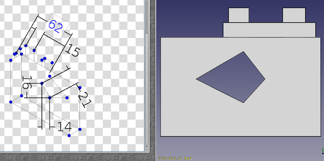
After about three weeks, of having to work on various assignments (nearing completion) and revision, I finally had a day off to work on dimension support in the Drawing Module (see above and compare to previous post).
Obviously the dimensions look much better and are correctly positioned and it also shares similar behaviour to sketcher where if the datum label lies outside the arrow lines change position accordingly.
Additionally the dimension can be set to the edge length in X or Y direction now quite easily by changing the dimension mode. Currently the dimensions only work for Straight Line edges, but I plan to address some support for vertexes and obviously circular arcs.
One of the interesting things that had to be thought was how to reference edges that are broken up into smaller segments by any geometry in front.
My first attempt at this failed miserably, where I thought I would reference each segment of the edge and find the ends from there but clearly it wouldn't work. After scratching my head, I thought the best way to go was getting the reference to the original geometry and projecting the whole edge and using this instead for dimensions.
The limitation with this strategy is that if the original reference isn't available you won't be able to get true parametric dimensions. Generally this isn't a problem - nearly all the time I have found references are available and if they aren't usually it is for curves projected onto a 3D view.
It was a bit of work to get to work, because I was using HLRBrep_Curve and that require figuring out what type of curve was produced when finished. I kept to this OpenCascade Algorithm to allow perspective projections if they were ever needed. Luckily it worked!
Behold Parametric Dimensions!
The big test really was to change the projection direction and see what happens...
And yes it worked - although the datum label positions need correcting, nothing else had to be changed. Now changing the geometry (nothing too drastic)...
It's a pleasing result because it's been several months in the works to get this working, not knowing if this would be even possible. Obviously there's a lot left to do.One of my biggest problems at the minute is that if there are changes in the Document Structure, the drawing view must be closed and re-opened
The next priority is to tidy the module up more as it's still feels experimental.


Hi Luke, this is looking great! Thank you for all the work you are putting into this module. For the circular arcs, would this be radius and diameter dimensions?
ReplyDeleteI am still working on something as simple as loading up an existing SVG template and displaying it on the page. I am finding I am quite a bit worse at C++ than I thought, you do more in a couple hours than I have in the past 3 weeks =D
Only one thing to say: AMAZING!!!!
ReplyDeleteI wouldn't think you'd have reached that far so soon, congrats!
It's really great that you're able to work on this very important functionality. Keep up the good work.
ReplyDeleteThe Google profile didn't add my nickname... The previous comment was from me.
ReplyDeleteNormandC
Fantastic work! FreeCAD is really coming along now thanks to you guys. Brilliant work!
ReplyDeleteFirstly thank you to everyone for the encouragement!
ReplyDelete@Joshua, keep it up - c++ is frustrating at first , but I was at the same point two years ago - it comes with practice. I need to still implement dimensions for arcs / circles , but it should be easy to set as a diameter or radius type. I'll keep looking at your repo, so far seems fine. What's your plan for the templates? Perhaps we could discuss this on IRC if you are free.
Phase 1: Get one of the existing SVG templates to display in the QGraphicsScene.
ReplyDeletePhase 2: Make FreeCAD editable text so.
Phase 3: Template editing mode?
Phase 4: Save and load templates as native QGraphicsItems?
I'm not really sure if those last two are the way to go. I think the templates should probably evolve into title blocks and title block management as well, but that is down the road.
I can be and often am on IRC around 4:00-4:30pm Pacific time.
The first two sounds sensible to start with and I Am sure was eventually going to be done anyway.
ReplyDeletei think when we get to title blocks this will need with some discussion. Having individual annotations will be straightforward to do and could be editable in place, but adding graphics and the title blocks may become problem if people want the title blocks to be easily customisable and exportable to other formats like dxf.
Thanks VERY much for this work - it's the primary feature that FreeCAD needs before it will be useful for real work in a non-CNC environment. Unfortunately, I seem to have encountered a problem with it (I get a hard, repeatable, crash every time I try to use it). I've done a gdb stacktrace and written up a bug report at:
ReplyDeletehttp://www.galleyrack.com/temp/parry-01/index.html
Hope this helps.
Regards,
David M. MacMillan
dmm at lemur dot com
www.CircuitousRoot.com
H David,
ReplyDeleteI was questioning what this could be and it's something that needs a little fix.
Basically before you click the add dimension button, you need to select an edge inside the drawing. (I have been lazy for not checking that the user provides an edge) and will eventually get around to it sometime.
Thank you for the diligent debug report. It's always good when users put effort into this.
Cheers
Luke